
Etch Factor is Comparable to Tooling Offset
Like other metal fabricating technologies, photo chemical etching requires adjustments of the nominal dimensions in order for the parts to come out the right size. In other processes, this may be referred to as tooling offset or a similar expression.
We refer to this adjustment as the "etch factor" and the process of applying the adjustment to the various dimensions of the parts as "compensation." If we did not compensate dimensions, the outsides of parts would be too small and the insides of parts would be too big. In some cases, where the metal is thin enough and the dimensional tolerances are generous enough, it may not be strictly necessary to apply the etch factor, however in most cases, we do.
For more detailed information:

Metal Thickness Affects Etch Factor
Just as the tolerance band and minimum feature sizes in photo etching are driven by metal thickness, so too is the etch factor. In it's simplest expression, and assuming a 50/50 etch, the etch factor is thickness/2.
Let's take the basic case of a washer. We will call the outside diameter 1" and the inside diameter .5 inches. If the selected metal is .010" thick, then we need to adjust the OD to be half the metal thickness larger, or 1.005". And, similarly, the ID needs to become .005" smaller or 0.495" on the phototool. Continuing this example, if the metal thickness is .020", then the compensated dimensions would be 1.010" and .490", respectively.
Keeping in mind that the clear areas on the phototool represent the actual part, we also apply an "etch band" to the areas to be etched. Depending on the metal thickness and the parts, the etch band that is printed in black on the phototool may be from .020" to .050" wide. If a part has large areas of internal cut-outs, we may put an etch band around the cut out and let it fall out, rather than put all of that metal into solution.
Even though we start with the customer's nominal data in the CAD file, the output on the phototool itself represents the process factors that are needed to produce the parts correctly as well as avoid putting metal into solution unnecessarily.
Asymmetrical Etching Ratios
The 50/50 etch represents the majority of etching applications, and this method is the typical strategy. There are situations where the standard methods must be modified to suit an alternative etching ratio.
In the cases where an asymmetrical etching ratio ( e.g., 60/40, 70/30, etc) is desirable, each side of the phototool must be compensated separately. In these cases, the etch factor is based on the fractional thickness of the metal, as if it were being etched from one side. So, in the example case of a 70/30 etch on .020" material, the 70% side (.020" x .7 = .014") is treated as the equivalent of etching .028 material 50/50 from two sides. Therefore, the compensation would be .028/2 or .014. The same rationale applies to the minor side, treating .006 from one side as if it were .012 from two sides, or .006".
Special Cases in Etching
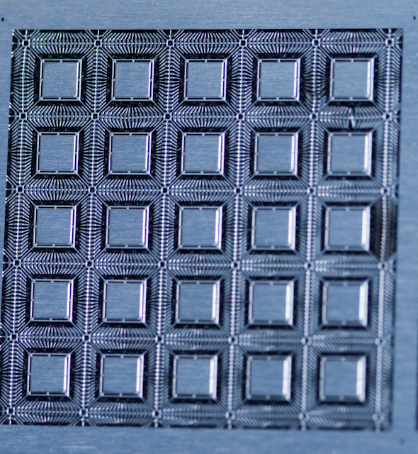
Although most applications can be served effectively with formulaic solutions for compensation, there are a growing number of designs, especially with regard to semiconductor packaging, that bring additional complexities to the process of compensating for the etch factors. This is particularly true for the so-called "flat, no lead" microleadframes. The "FN" style leadframes, whether "quad" (QFN) or "dual" (DFN), require an heuristic approach to compensation, since the parts involve both partial and full thickness etching in different areas. What may be predicted by calculation, may not prove out in process. This leads to "measure, modify and make again." 
As chip technology continues to evolve, newer packaging variants, including thin (T), ultra thin (UT) and extremely thin (X) pose additional challenges to variable compensation.